Shooting on the Move: An Iterative Solution
A moving robot changes a ball’s trajectory. Compensating for that motion changes its flight time. Here’s how to solve the circular dependency with an iterative shot model.
Getting a robot to shoot accurately at a target is a well-understood problem. With some high-school physics, empirical tuning, and a consistent shooter, we can predict the angle and exit speed for a stationary shot. Once the robot starts moving, though, the ball inherits that motion too.
The extra displacement depends on how long the ball is in the air. Compensating for it changes the shot, which changes the time of flight. That circular dependency is the problem we need to solve.
Stationary shots
Start with a stationary robot. Let v be the ball’s exit speed, θ its launch angle above horizontal, and g = 9.81 m/s². Measure height from the shooter’s release point, so the goal is at height h relative to that point. Ignoring air resistance and spin, the ball follows:
Many combinations of speed and angle can pass through the same target. A speed limit narrows those choices, and the goal geometry narrows them further. For a goal that the ball must enter from above, crossing the target height on the way up does not count.
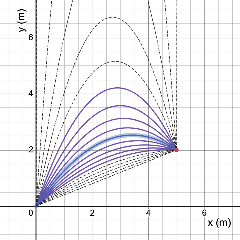
In practice, a table of measured shots can account for effects that this simple model misses. We’ll assume we have a way to look up exit speed v(d) and angle θ(d) for a horizontal distance d. These could come from equations or from interpolation between tested shots. The target height is fixed.
Moving frames
Throw a ball from a moving train and it inherits the train’s velocity. The same happens on a robot. At release, the ball’s field-relative velocity is the sum of its velocity relative to the shooter and the shooter’s own velocity:
Here u is the horizontal velocity of the release point in field coordinates. For now, assume the robot is translating on a level floor. If it is rotating and the shooter is offset from its center, the release point also has velocity from that rotation.
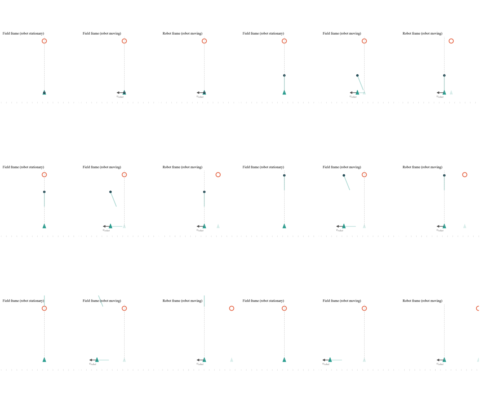
The robot does not keep pushing the ball after release. If it brakes or changes direction, the ball continues along its own trajectory. In the ideal ballistic model, the displacement added by the initial robot velocity is u times the flight time.
If we could command any launch velocity, we could simply subtract u from the desired field velocity. But our tuned shooter gives us a particular speed and angle for each distance. We want to keep using that shot table, changing its distance input and the horizontal aim, or yaw.
Turn velocity into a target offset
Let r be the horizontal vector from the release point to the real target. If the ball spends T seconds in flight, aim at a virtual target shifted opposite the robot’s velocity:
The double bars mean vector length. A stationary shot toward this virtual target covers r_eff; the inherited velocity supplies the remaining displacement uT. Together they reach r.
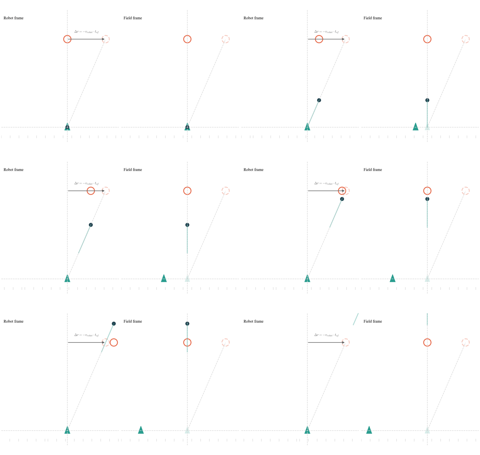
This must be a vector calculation. Moving toward the goal reduces the effective distance; moving away increases it. Sideways motion changes both the aim and the effective distance. Subtracting speed times flight time from the original scalar distance only describes motion along the target direction.
The time-of-flight loop
For a chosen stationary shot, vertical motion gives us the flight time. Define w(d) as the vertical component of exit velocity. Solving for when the ball reaches the target height gives:
We choose the plus sign for the later, descending intersection. A negative discriminant means the shot never reaches the target height; a zero discriminant reaches it at the apex, with no downward velocity. Neither is a usable descending shot into this goal.
That calculation is straightforward when d is known. For a moving shot, however, d is itself a function of T:
The quadratic formula still solves the vertical motion for any one selected shot. It does not resolve the whole problem, because selecting the shot requires the answer. With an arbitrary lookup table, we generally need a numerical solution.
An iterative solution
Try entering a number into a calculator in radians and repeatedly pressing cosine. The sequence approaches 0.739085…, a solution of x = cos(x). This is fixed-point iteration: use the current answer as the next input.
We can do the same with flight time. Start with the stationary shot at the real distance, use its flight time to offset the target, then look up the shot for that new distance:
Each pass updates the displacement using the flight time of the previous pass. When the estimates settle, the chosen trajectory and the displacement correction agree. One pass may be a useful approximation, but it is not a guarantee of accuracy. Convergence depends on robot speed and how quickly the shot table’s flight time changes with distance.
Limit the number of iterations, reject distances outside the calibrated table, and check the remaining disagreement. Near a fixed point, iteration is locally convergent when the magnitude of the slope of F(T) = T(‖r − uT‖) is less than one. A table discontinuity or a large velocity can make this fail.
Adjusting yaw
Once we have a flight-time estimate, aim along r_eff. In field coordinates, atan2 gives the heading while preserving the correct quadrant:
For a turret command relative to the robot, subtract the robot’s heading and wrap the result to the turret’s angle convention. The subscripts x and y here are the two horizontal field axes, not the vertical coordinate used in the earlier projectile equations.
We can also look at the sideways velocity directly. If φ is the yaw offset from the original target direction, and u_lateral is the robot velocity perpendicular to that direction, lateral cancellation requires:
Flight time cancels from both sides of this lateral equation. It still matters for the effective distance and the selected shot. Using the full offset vector handles these two adjustments together.
Putting it into code
The following pseudocode uses field-relative vectors and a stationary shot lookup that includes flight time. That time can come from the ballistic equation above or from measurements paired with the same calibrated shot. Tolerances and iteration limits need to be chosen for the actual robot.
r = targetPosition − releasePosition
if length(r) is outside calibrated range:
    return NO_SHOT
initialShot = lookupShot(length(r))
if initialShot is invalid or initialShot.flightTime <= 0:
    return NO_SHOT
T = initialShot.flightTime

for each iteration up to MAX_ITERATIONS:
    aim = r − releaseVelocity * T
    if length(aim) is outside calibrated range:
        return NO_SHOT

    shot = lookupShot(length(aim))
    if shot is invalid or shot.flightTime <= 0:
        return NO_SHOT

    nextT = shot.flightTime
    timeError = abs(nextT − T)
    displacementError = length(releaseVelocity) * timeError

    if timeError < TIME_TOLERANCE and
       displacementError < POSITION_TOLERANCE:
        return shot.speed, shot.angle, atan2(aim.y, aim.x)

    T = nextT

return NO_SHOT
All inputs and results must be finite. A failed solution should inhibit firing or fall back to a separately validated stationary shot, rather than use the last estimate unchecked.
Use the estimated position and velocity at release, accounting for the delay between issuing a command and the ball leaving the shooter. Keep units and reference frames consistent. If rotation matters, include the release point’s tangential velocity, ω × offset, in u.
What the model leaves out
This derivation is exact for ideal ballistic motion when the stationary shot model and flight time are consistent. A measured table can improve the stationary model, but air resistance and spin can make a moving shot behave differently: the ball’s velocity relative to the air changes when the robot moves. Pose error, velocity estimates, release timing, and shooter repeatability also affect accuracy.
The useful idea is to turn motion compensation into a small loop around a stationary shot model: estimate flight time, shift the target, select a shot, and repeat. Test it across the distances and driving speeds you intend to use, and only fire inside the range where the whole system is reliable.